Page 1 of 1 · 4 of 4 publications

MAR 05 2022

Elegoo Mars 2 Pro Resin Printer

Thanks to the lovely people at Elegoo, we now have a resin printer for the members to use. After much reading up on how to handle resin (which is toxic so you shouldn’t get it on your skin), we designed a process to use it, and taught some members.

One of the first was Matt, who videoed the process for us:

We were generously sent an Elegoo Mars 2 Pro printer, a curing station and a bottle of water washable resin.

NOV 14 2018

Member Project: Slide Hammer

Aka: The Shiv of Self Love (The Wanky Wanky Shiv) Stats Made by: Josh and Steve Status: Finished Tools used: 3-in-1 lathe, TIG Welder Description Well it started as an oil change and before we knew it we were removing the apron from the Colchester Triumph 2000 lathe, but more on that later. In order to remove the apron we needed to take the lead screw and feed shafts off. Disconnected at the thread cutting gear box side all that was holding them in was a bracket on the right of the machine. In turn this is secured by two screws and two dowels. The screws were easy enough to remove, the dowels less so. They are an interference fit but have a thread in the centre to which it is intended to connect to and using a slide hammer pull them out. So the simple plan was to insert a bolt and pull them out, trouble was a M4 bolt was too small and a M5 had the wrong thread. Then it dawned on us, imperial. Trouble was at this point we had half disassembled the lathe and realised that we had neither an imperial bolt of the correct size, nor a slide hammer. Looks like we were going to have to MacGyver our way out of this one…

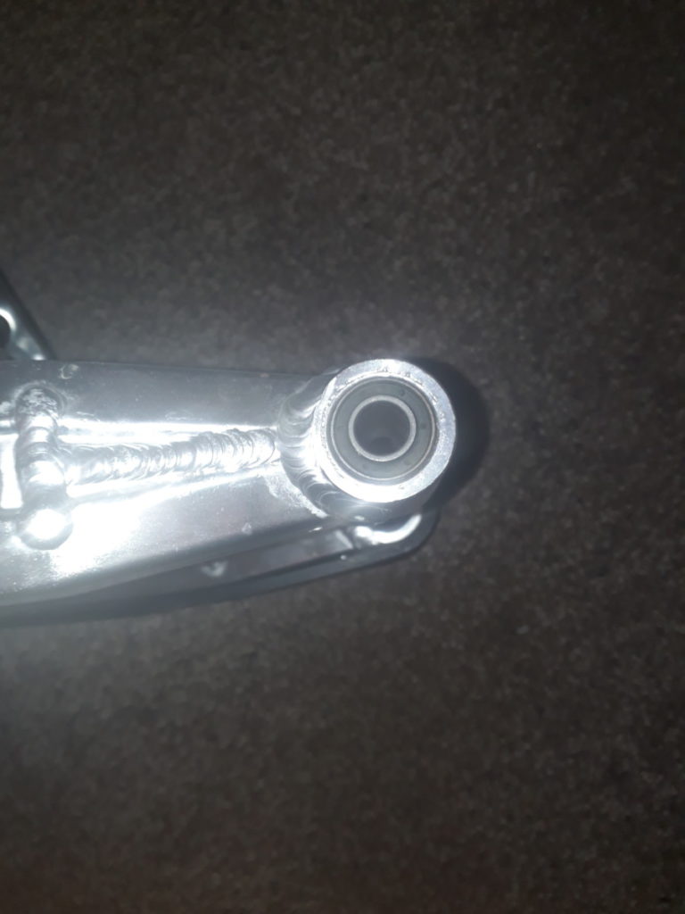
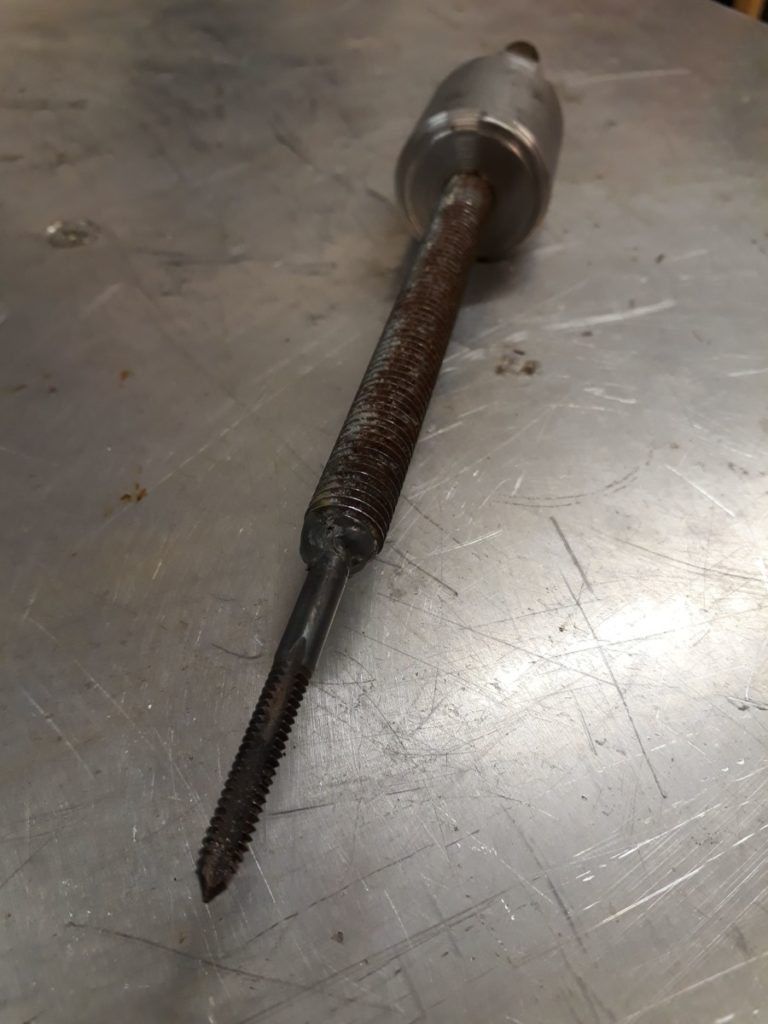
Welding the tap to the shaft

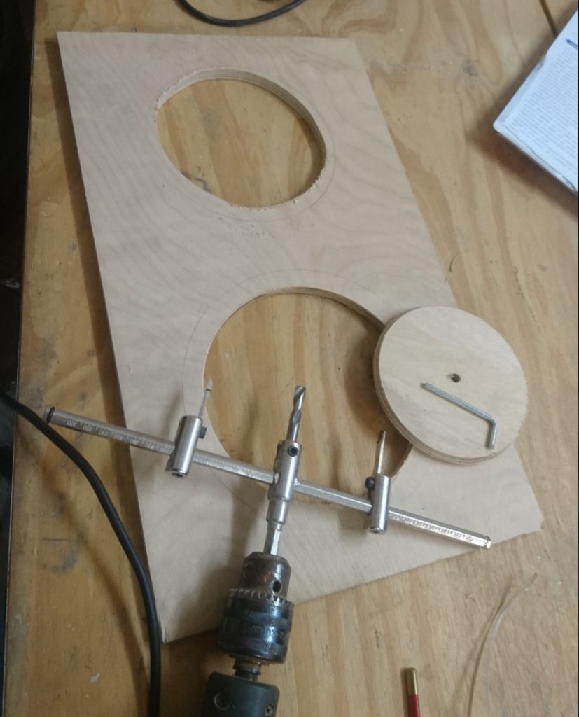
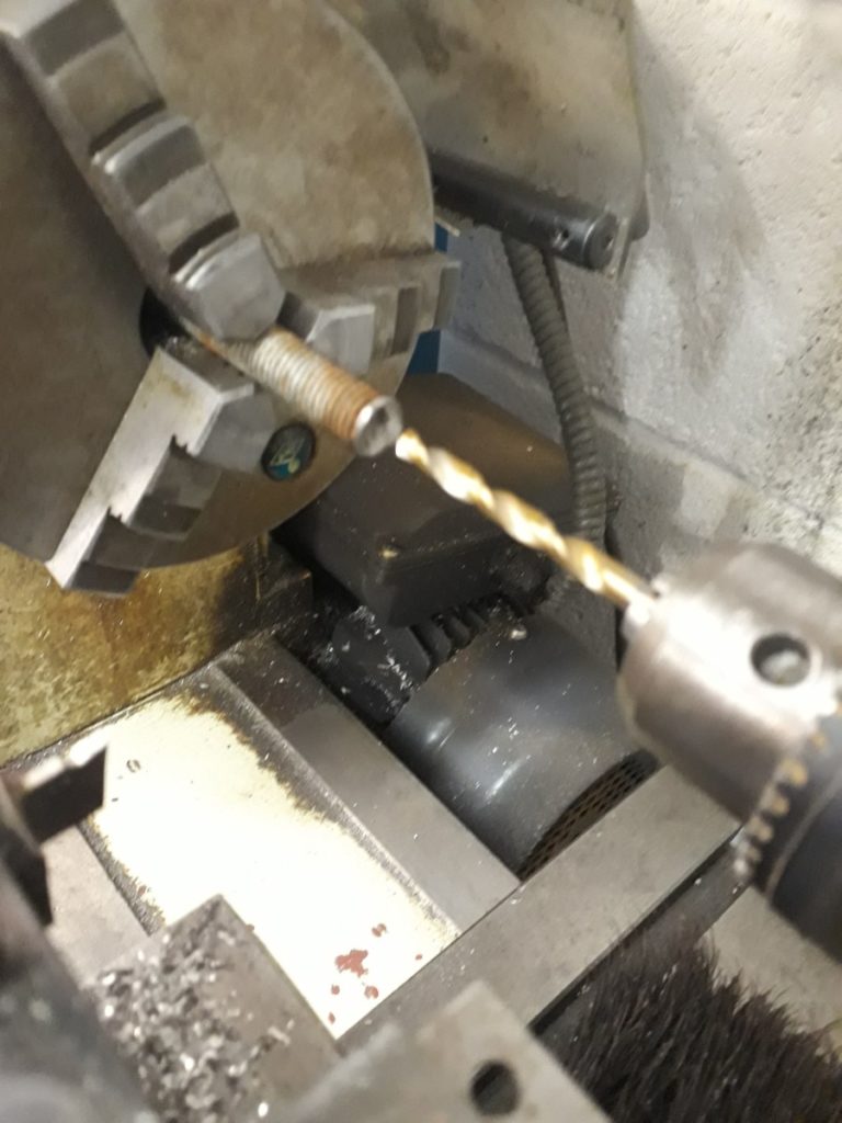
Sure enough after some trial and error we located a tap of the correct size and pitch (though we’ve forgotten to make a note of that size and we don’t have an imperial thread gauge). Now we had something to attach to the dowel we needed a slide hammer and this is where the threaded rod came into play. Manually cutting a shorter length of rod to use we took the rod to the 3-in-1 lathe and started with a centre drill before moving to a 5.5mm drill bit to 10mm depth at one end.

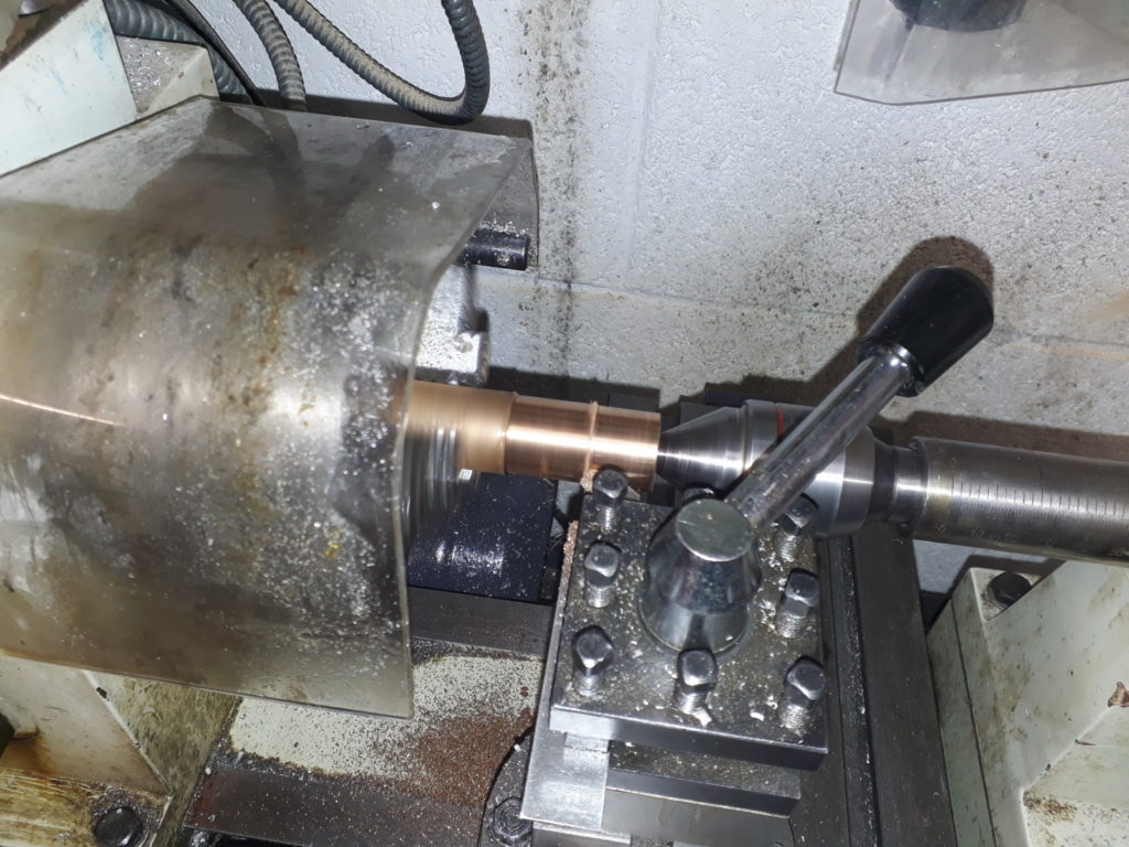
Drilling the bore of the side

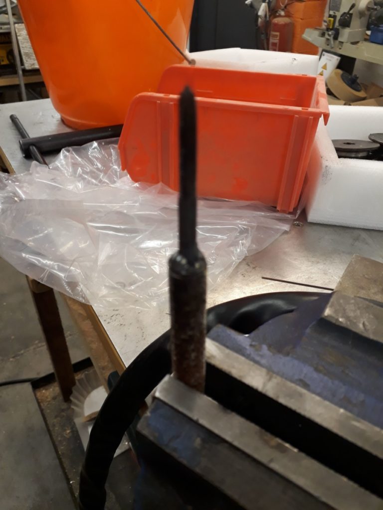
This little recess was now the correct size for the tap to sit in. But we needed to secure it so Josh broke out the TIG Welder and welded the tap to the rod. This formed the shaft of our slide hammer, and a nut was added to the non-tap end to act as the hammer stop. All we needed now was a slide.

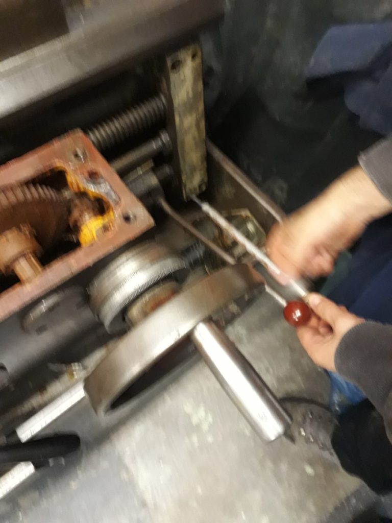
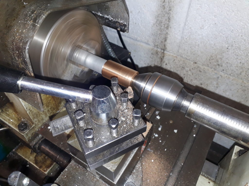
Using the slide hammer to remove the dowels

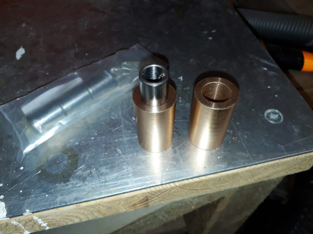
A quick raid of the metal stock found a small steel cylinder that had already been drilled through to around 6mm. However we needed a 12mm hole and this is where we hit another problem, the biggest drill bit we could locate was 10mm. Undeterred we embiggened the hole to 10mm on the 3-in-1 lathe. And then finally using a 12mm end mill the hole was taken to the correct diameter.
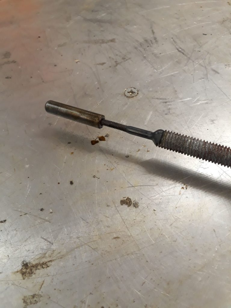
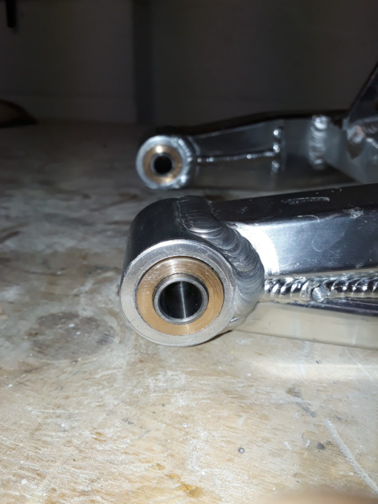
The removed dowel

Our slide hammer was now complete, so back to the Colchester it was. Tap end well inserted only a few hits were needed and the dowels were free. The bracket, shafts, and apron could then be removed

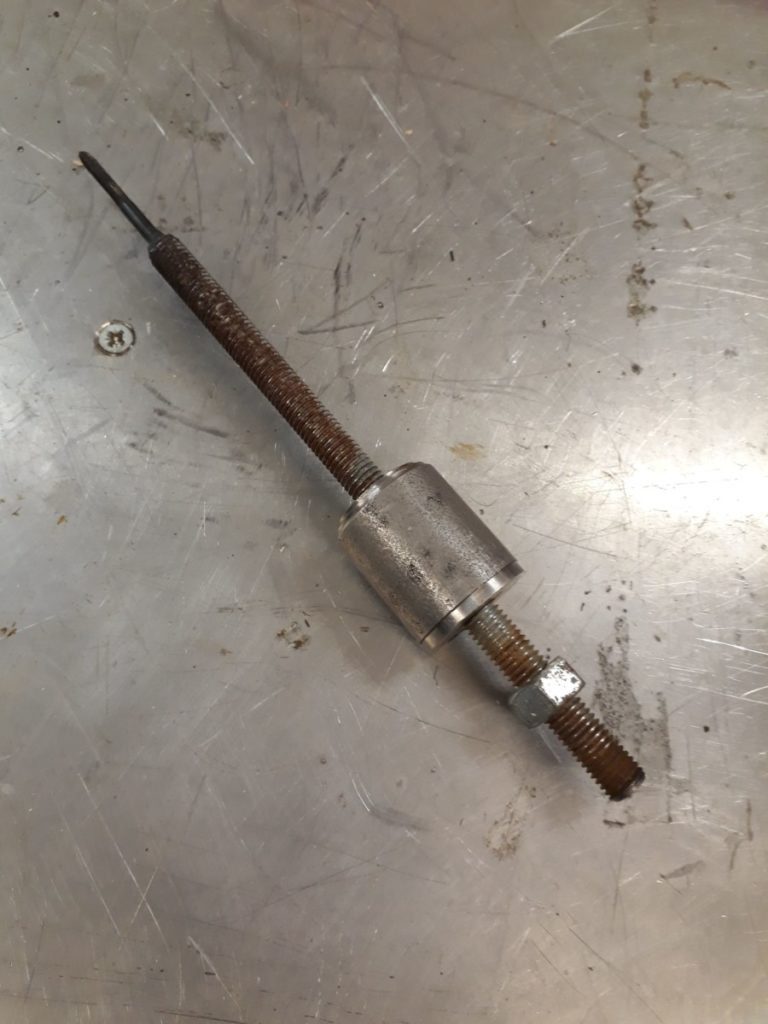
The slide hammer competed

Creation of the slide hammer was fairly straight forward and was made even easier with the two of us working together, Josh on the Welder, me on the 3-in-1 lathe. However, with a little more planning we might not have ended up needing to fabricate this tool. But it was a bit of fun to do and is a tool that will live with the Colchester in case we need to remove the shafts again which I hope we don’t.

This side hammer is awesome

SEP 23 2018

Member Project: Swingarm Bushing

Stats
  • Made By: Steve
  • Status: Finished
  • Tools used: 3-in-1 lathe, 16mm reamer, Arbour Press
Description

I have a Honda Grom and like any good motorcyclist I take pride in modifying my bike. This modification involves replacing the standard steel swingarm with a Tyga aluminium over braced item. This is a straight swap however I wasn’t happy with the new arm as it had like the OEM arm rubber bushing at the pivot instead of roller bearings that I would expect.

Bought replacement Swingarm

Bought replacement Swingarm

The problem here was that despite my best googlefu and the help of a local bearing suppliers I couldn’t locate a set of roller bearings at the correct size that being 12mm ID and 24mm OD by 42mm length. So having already removed the rubber bushing I decided the best solution here would be to turn some bronze bushing to size to remove the flex of the rubber bushes.

So I ordered some oilite bronze stock and headed to the 3-in-1 lathe. Checking my feeds and speeds I turned the rpms down on the lathe and set about turning the outside of the stock down to fit. With that set it was time to drill the internal diameter to 16mm to fit a pair of needle roller bearing internal sleeves.

Bronze stock on the 3-in-1 Lathe

Bronze stock on the 3-in-1 Lathe

And this is where I made a mistake. Drilling the centre out to 16mm resulted in the internal sleeve simply slipping through the hole. Turns out twist drills are not that accurate. So I started again, this time drilling to 15mm and then finishing off by hand with a 16 mm reamer. The sleeve now fitted perfectly.

Two attempts to drill

Two attempts to drill

Next was to put the bush into the swing arm where by I found the next problem. While one hole was 24mm the other was around 23.5mm so was to big to fit. I solved this by putting the bush back into the lathe held by a live end in the tail stock and dead end in the chuck to enable me to hold the part while being able to work the length of the piece.

Retry on the diameter

Retry on the diameter

Finally with both bushes the right diameter I used the Arbour press to insert them securly into the arm and then fitted the arm to the bike.

Bushes inserted into Swingarm

Bushes inserted into Swingarm

These were made in a few hours over the course of a couple of visits to the space. I could have completed this in one evening if I didn’t have to wait for my new reamer to arrive.


AUG 16 2018

Member Project: Dog food and water table

Stats
  • Made by: Jess
  • Status: Finished
  • Tools used: Mitre Saw, Powered Screwdriver, Trepanning Tool (new!), Polyurethane spray varnish

Description

My old dog is getting a bit unsteady, and often ends up sitting on her food and water bowls. The existing tray (which I added legs to a while ago) has gotten all soggy, and lost its bordering edge, so the water bowl ends up all over the floor.

The replacement needed to be more waterproof, taller, and keep the bowls in place, even when lent or sat on. I decided to cut circles out of the new top to sit the bowls in, and spray the whole thing with a waterproof varnish.

Trepanning Tool and holes in board

Trepanning Tool

The whole thing is made out of scrap wood from the Makerspace wood store. To make the circles I added a new tool to the space, a Trepanning Tool, which is attached to a powered drill and cuts a hole using two extra blades. It looks quite scary when spinning and takes a while to cut through the 6mm plywood. (Josh helped with this bit!)

The rest is assembled with legs cut to size and screwed together. The spray was the applied, which was dryish in an hour, and dry 24hours later.

So far it seems to be working, the doggo has only managed to slop some water, and not dump the whole thing on the floor.


Dog food and water table

Dog food and water table

This took me a couple of visits to the space, could probably have been done in one if I didn’t keep getting distracted. Some folks helped me out, which was good motivation. Now I don’t have to keep mopping the kitchen floor!